English
Views: 0 Author: Site Editor Publish Time: 2026-07-05 Origin: Site
Hardware engineers constantly face a frustrating design bottleneck during product development. They must balance strict physical space constraints against the urgent demand for reliable, high-gain RF signal reception. Shrinking device footprints leave virtually no room for bulky internal components. Yet, portable units still require robust VHF and UHF capabilities to function properly in the field. Without the right hardware, signal drops and mechanical failures quickly ruin the end-user experience. You need a reliable solution balancing spatial flexibility and physical ruggedness.
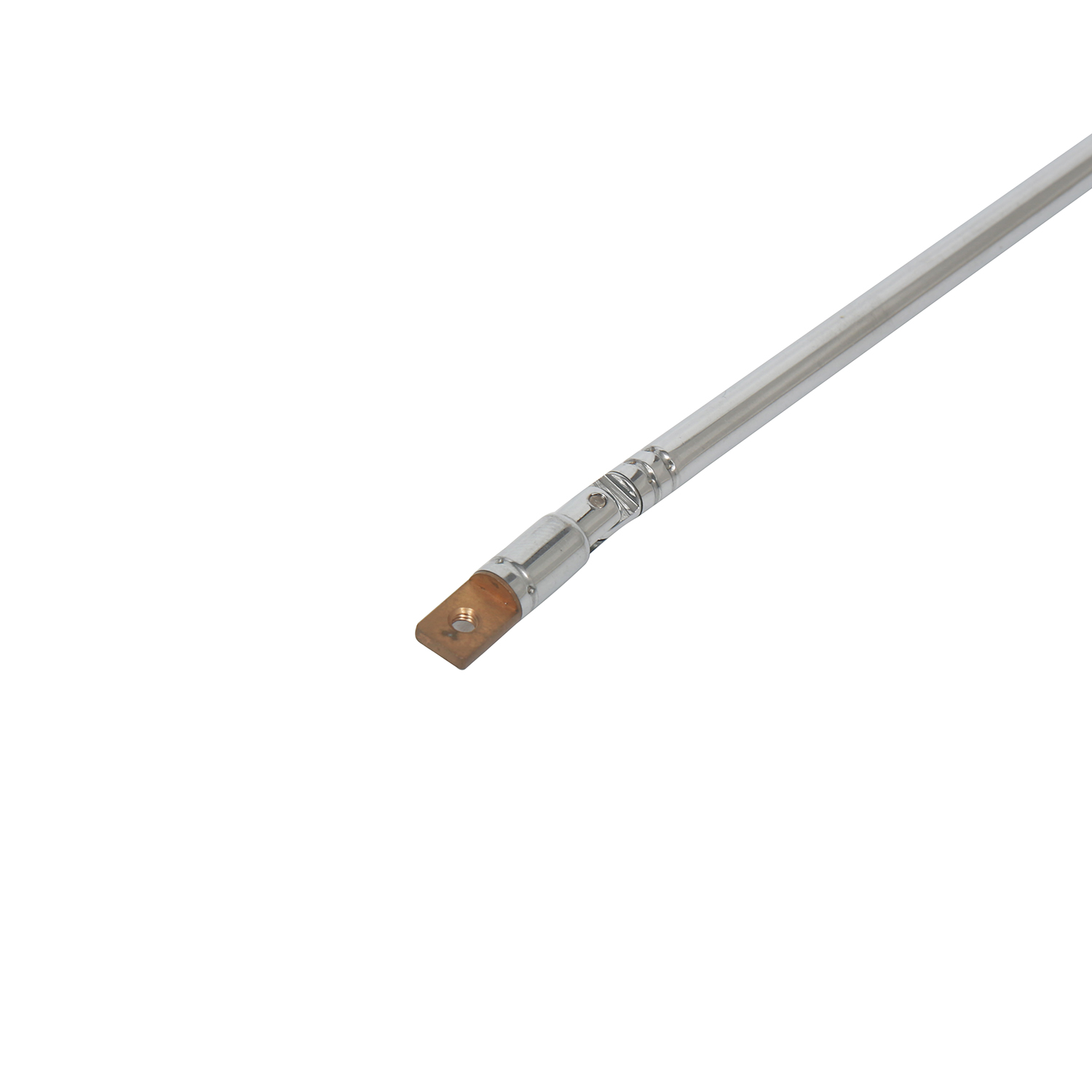
The stainless steel telescopic antenna serves as the undisputed industry standard for overcoming these exact limitations. It delivers exceptional mechanical durability and variable-frequency tuning out of the box. This component easily outperforms fixed-length rods or cheaper brass alternatives. It adapts effortlessly to changing frequency needs while surviving harsh outdoor field deployments.
This guide provides a complete technical evaluation framework for your team. We will help hardware engineers and procurement officers confidently shortlist antenna components for upcoming product runs. You will learn how to properly assess material strength, mechanical tolerances, and critical electrical specifications.
Older communication devices heavily relied on brass or copper alloys for their external components. These softer metals bend incredibly easily under moderate physical pressure. Field operators often snap them accidentally during rapid deployment. Environmental corrosion also destroys softer metals quickly in high-humidity or coastal areas. Stainless steel changes this structural dynamic completely. It resists snapping and holds its shape under severe bending stress. Devices survive outdoor field use much longer when utilizing high-grade steel tubing.
Engineers often question the electrical conductivity profile of steel alternatives. Pure copper certainly conducts electricity far better than raw steel. However, raw conductivity does not dictate overall RF performance alone. The skin effect governs how high-frequency signals travel along the outer surface of a conductor. Engineers combine a strong stainless steel shaft incorporating proper base plating. Applying nickel or gold directly at the connector interface bridges the conductivity gap perfectly. This hybrid manufacturing approach yields the optimal balance. You get extreme mechanical strength without sacrificing your RF transmission clarity.
Telescopic joints face a harsh mechanical reality every day. Users extend and collapse them thousands of times throughout a product lifecycle. Cheaper metals wear down fast due to constant metal-on-metal friction. Their internal friction sleeves degrade rapidly. Soon, the entire structure collapses under its own weight. Stainless steel maintains highly consistent internal friction. It heavily resists galling and scratching across thousands of duty cycles. Your device stays fully extended even in demanding, high-vibration conditions.
Extending or retracting the internal sections directly changes the physical length of the mast. This simple mechanical action adjusts the resonant frequency instantly. Wideband receivers rely on this exact physical flexibility to operate across different bands. Users easily tune the hardware manually to capture specific incoming wavelengths. A fully extended mast captures lower frequencies efficiently. A partially collapsed mast tunes precisely into higher frequency bands.
Evaluating physical dimensions dictates your overall integration success. Collapsed length proves incredibly crucial for internal housing inside modern, compact devices. You must ensure the fully retracted mast fits inside your chassis. Extended length dictates the maximum signal capture capability of the receiver. Section count plays a massive role in this dimensional balancing act. You must weigh compact housing against mechanical complexity during the design phase.
| Design Type | Collapsed Profile | Extended Reach | Mechanical Joints | Best Use Case |
|---|---|---|---|---|
| 7-Section Standard | Moderate | Long | Fewer (Higher rigidity) | Handheld transceivers, CB radios |
| 10-Section Compact | Ultra-short | Moderate to Long | More (Lower rigidity) | Compact scanners, IoT gateways |
| 5-Section Heavy Duty | Long | Very Long | Minimal (Maximum strength) | Stationary testing equipment |
The internal RF circuit demands proper impedance matching to function correctly. Most commercial applications expect standard 50-ohm or 75-ohm impedance parameters from the port. These specific components naturally offer base-level omnidirectional gain. They pull incoming signals from all directions simultaneously. You do not need to aim them perfectly at the transmission source to establish a connection.
Field deployment demands rugged, reliable communication gear. We see heavy integration across commercial CB radios and digital scanners. Portable transceivers rely entirely on a robust telescopic pole antenna to maintain critical lifelines in remote geographical areas. Emergency responders depend on their physical durability daily during crisis management. The ability to manually tune the mast saves lives when navigating heavily disrupted frequency bands.
This hardware adapts beautifully for broader consumer goods as well. Manufacturers frequently implement it as an electric appliance antenna for standard AM/FM receivers. Remote control transmitters need them for pushing strong sub-GHz output commands over long distances. Smart home hubs and IoT gateways requiring external manual adjustment also benefit greatly from this simple integration.
Laboratory environments require high precision and total reliability. Spectrum analyzers and sophisticated RF diagnostic tools use these components constantly. Technicians need adjustable lengths to monitor varying signal emissions properly. Changing the physical length helps them isolate specific frequency bands during complex network testing. This manual isolation prevents overlapping signals from corrupting sensitive diagnostic data.
Every physical component has strict breaking points. You must acknowledge these mechanical limits early in your design cycle. Extreme lateral force will bend a fully extended multi-section shaft permanently. Heavy side impacts can easily snap the thinnest top section off completely. Engineers should always design protective base shrouds to mitigate side-loading impacts. Adding a reinforced rubber grommet at the exit port absorbs significant mechanical shock.
Manage your data throughput expectations carefully. We must contrast these manual models against advanced MIMO (Multiple-Input Multiple-Output) arrays found in modern routers.
Poor grounding destroys signal integrity instantly. You face massive grounding challenges if you ignore the primary mount point. Proper printed circuit board (PCB) grounding prevents unwanted signal noise from entering the receiver. It also fixes dangerous impedance mismatches causing power reflection. Ensure your internal ground plane matches the intended operating frequency perfectly. A solid counterpoise guarantees the mast operates at peak electrical efficiency.
You must verify the exact base mount before initiating any purchase orders. Look closely at your device casing and internal PCB layout. Common standardized interfaces include the BNC male connector, threaded SMA ports, or internal screw and solder lugs. A mismatched connector delays production runs by several weeks. Always confirm the thread pitch and barrel length match your housing tolerances exactly.
Regulatory compliance matters significantly for global distribution. Highlight the need for strict RoHS certification when speaking to suppliers. Tight manufacturing tolerances prevent loose joints right out of the box. High-quality precision stamping ensures smooth friction during every extension. Poorly stamped sleeves cause a gritty feeling and premature mechanical failure.
Never commit to bulk B2B procurement blindly. Always request minimum-order samples first to validate vendor claims. Conduct rigorous physical cycle testing in your own laboratory.
A stainless steel component delivers proven, durable performance across countless industries. It remains the top structural solution for variable-frequency RF applications requiring manual user adjustment. By choosing high-grade alloys, you eliminate the common bending and corrosion issues plaguing cheaper brass alternatives. Your end-users gain a reliable interface handling thousands of deployment cycles smoothly.
Audit your device's physical housing limits immediately to determine maximum collapsed length constraints. Confirm your specific frequency band requirements to calculate the necessary extended mast length. Finally, request technical specification sheets and physical testing samples from vetted, high-quality manufacturers. Proactive testing ensures your next product launch delivers flawless communication reliability.
A: A 10-section design achieves a much shorter collapsed length. This compact footprint fits easily into tight device housings. It provides excellent portability without sacrificing the total extended length required for optimal signal reception. However, more sections introduce additional mechanical friction points.
A: The outer material primarily dictates physical durability and corrosion resistance. While pure copper is highly conductive, the base connection and internal conductive plating handle the primary RF load. High-quality base plating ensures excellent signal transfer despite the rigid stainless steel exterior.
A: Yes. While Wi-Fi and Bluetooth typically use internal fixed components, telescopic versions remain highly relevant. They provide essential connectivity for sub-GHz RF remotes, traditional FM radios, and specific long-range IoT hubs requiring external signal tuning.
A: Preventing looseness starts during the B2B purchasing phase. You must select high-grade stainless steel models featuring precision-stamped internal friction sleeves. Rigorous factory quality control ensures these internal sleeves maintain constant pressure across thousands of extension cycles.