English
Views: 0 Author: Site Editor Publish Time: 2026-07-09 Origin: Site
Hardware development often forces a tense compromise between speed and performance. Off-the-shelf components certainly accelerate early prototyping. However, they frequently introduce critical RF compromises during final device integration. You must constantly balance variable frequency requirements against strict spatial constraints. This is where a custom telescopic antenna becomes incredibly valuable for modern OEM electronics. Portable radios, IoT devices, and specialized testing equipment demand absolute precision. Standard parts rarely deliver consistent results inside unique, tightly packed enclosures.
We designed this article to provide OEM product managers and RF engineers with a practical, evidence-based framework. You will learn exactly when and why a tailored approach reduces compliance risks and minimizes field failure rates. By understanding the underlying mechanical and electromagnetic variables, you can make smarter design choices early in the product lifecycle. A well-planned RF strategy prevents costly redesigns and ensures your final product connects reliably in the real world.
Many engineering teams fall into the "good enough" fallacy during the early stages of product development. Standard antennas undergo testing in perfect laboratory conditions. Component manufacturers usually measure them in free space or mount them on massive, idealized ground planes. These flawless environments never match your actual OEM device enclosure. When you drop a generic part into a tight plastic or metal housing, its electromagnetic performance shifts dramatically.
Proximity to other internal components actively destroys idealized radiation patterns. Batteries, liquid crystal displays (LCDs), and dense metallic casings act as parasitic elements. They pull the resonant frequency far away from your target communication band. This detuning process severely degrades overall signal strength. A standard component might show excellent gain on a published datasheet. Inside your physical product, it often struggles to maintain a stable connection.
Opting for standard designs often creates hidden financial traps later in the development cycle. Failed pre-compliance testing represents a massive risk. When devices fail regulatory emissions testing, engineering teams face weeks of frantic redesign work. Product recalls due to poor field range also destroy brand reputation and consumer trust. The slightly higher initial non-recurring engineering (NRE) cost of a custom design acts as a powerful insurance policy. It protects your project against these catastrophic late-stage failures and delays.
| Design Variable | Off-the-Shelf Component | Custom Engineered Component |
|---|---|---|
| Ground Plane Availability | Matches standard datasheet specifications perfectly | Highly restricted, asymmetric, or non-standard shape |
| Enclosure Material | Standard plastic with ample internal clearance | Metal casings, metallic paints, tight component proximity |
| Target Frequency | Single standard commercial band (e.g., 2.4 GHz) | Multi-band or highly specific narrow frequencies |
| Mechanical Clearances | Ample external clearance and mounting space | Strict internal retraction and form factor requirements |
Radio frequency engineering requires exact impedance matching to maximize power transfer. You must tune the system to achieve a remarkably low Voltage Standing Wave Ratio (VSWR). Standard models assume a perfect 50-ohm system environment. Your unique printed circuit board (PCB) and ground plane size rarely provide this ideal matching natively. Custom tuning adjusts the feed point impedance specifically for your physical layout. This precision minimizes reflected power, protects your transmitter amplifier, and extends battery life.
You cannot rely on generic segment lengths for specialized communication applications. Custom lengths allow RF engineers to target extremely specific, narrow frequency bands. Some industrial devices require reliable multi-band performance without experiencing dead zones. Base loading coils become essential design elements here. They electrically lengthen the element while keeping the physical profile surprisingly short. Tailored engineering determines the exact inductance values needed for your specific bandwidth requirements.
An antenna operates as a mechanical device just as much as an electrical one. Metal tube thickness dictates the structural rigidity of the entire assembly. Joint friction controls how smoothly the sections extend and remain securely in place. Material choice dictates the operational lifecycle of these moving parts. Using a stainless steel antenna pole provides superior corrosion resistance for harsh outdoor environments. Stainless steel actively prevents joint oxidation. Oxidation severely degrades consistent RF conductivity over thousands of uses. Brass or copper alternatives often fail these stringent environmental tests rapidly.
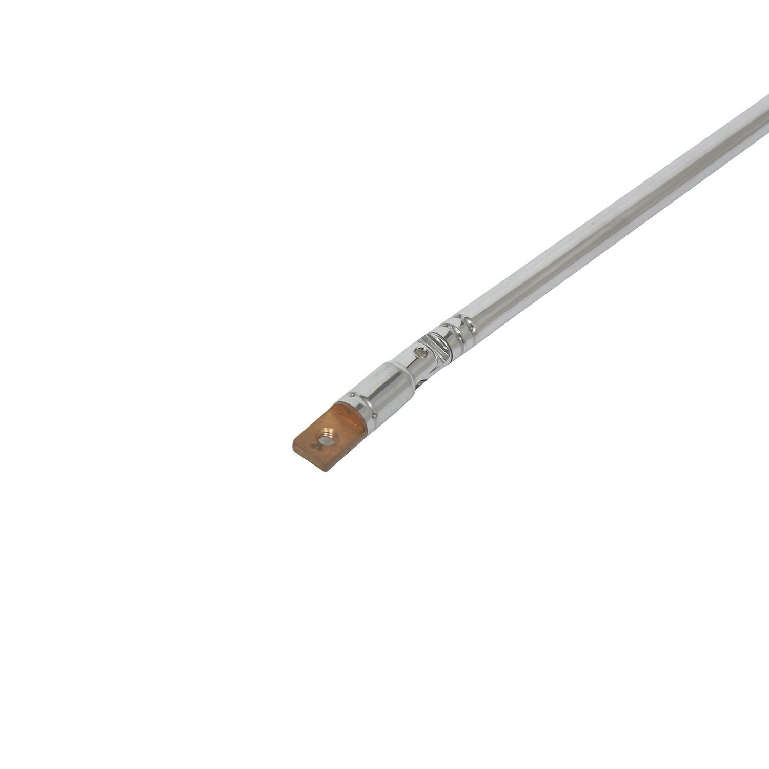
Original equipment manufacturer devices shrink in size every single year. Internal spatial constraints are fiercely contested by competing hardware modules. Custom designing the nested sections of a collapsible telescopic antenna ensures perfect physical integration. It retracts fully into restricted device housings without impacting other modules. Precise length control guarantees the metal tip will not accidentally short out delicate internal components when pushed completely downward. This crucial level of mechanical safety remains impossible to guarantee with generic, unoptimized parts.
Every physical object placed near your radiating element creates parasitic capacitance. This enclosure effect fundamentally alters how the electromagnetic field propagates through space. Standard connectors often introduce unwanted signal loss exactly at the connection point. Custom base mounts engineered for your specific casing directly mitigate this loss. You can specify custom SMA, BNC, or proprietary pogo-pin connectors during the design phase. These tailored connections maintain strict impedance continuity from the PCB trace right up into the radiating metal.
Global regulatory bodies enforce strict limits on electromagnetic emissions and immunity. Certifications from the FCC, CE, and IC remain mandatory for legal market entry. Custom manufacturers proactively design with these strict regulatory limits in mind from day one. They suppress spurious emissions structurally through precise geometry. They optimize the radiation pattern to focus energy exactly where needed, rather than leaking it into adjacent restricted bands. This proactive methodology drastically simplifies your final laboratory certification process.
Basic laboratory testing represents a purely passive environment. Real-world usage scenarios are highly active and unpredictable. User interaction fundamentally changes device physics. Hand effects on portable radios or handheld test equipment severely detune the resonant frequency. Human tissue acts as a dielectric material that absorbs RF energy. Custom radiation pattern modeling actively mitigates this severe detuning effect. Engineers simulate how the device behaves when physically held. They subsequently shift the baseline tuning so peak RF performance aligns with the active, in-hand state rather than the passive desktop state.
Transitioning from a rough concept to a mass-produced component requires a highly disciplined workflow. Knowing these sequential steps helps OEM teams accurately align their internal project timelines. A structured approach eliminates guesswork and prevents expensive tooling errors.
Not all component suppliers possess genuine RF engineering capabilities. Many simply bend and cut metal. You must rigorously evaluate potential partners to ensure product success. Use the following criteria to separate simple metal fabricators from highly capable engineering partners.
A custom antenna is far more than a simple telescoping metal rod. It operates as a highly sensitive radio frequency component completely critical to your product's overall market success. Treating it as an afterthought almost guarantees massive integration headaches. We strongly advise hardware engineering teams to involve specialized manufacturers during the initial PCB layout phase. Do not wait until the mechanical housing is permanently locked and injection molding tooling is finalized. Early collaboration solves severe impedance mismatches before they mutate into expensive hardware revisions.
You can achieve significantly better range, battery life, and durability by stepping away from generic catalog parts. Secure your competitive advantage by prioritizing precise RF engineering over perceived short-term convenience. Contact us today to thoroughly discuss your telescopic antenna needs. Request a comprehensive custom capability assessment to see exactly how tailored components can elevate your next major product release.
A: Standard timelines usually range from three to six weeks. This depends heavily on mechanical complexity and required RF simulations. Simple length adjustments take less time. Complex designs requiring new base loading coils, specialized connectors, or intensive anechoic chamber testing will push the timeline toward the six-week mark.
A: While MOQs exist to cover initial setup and tooling costs, they are rarely restrictive for serious OEM projects. Manufacturers commonly run smaller pilot batches for beta testing. These pilot runs allow you to validate real-world field performance before committing to large-scale mass production volumes.
A: Yes, but physical limitations always apply. Engineers use specialized base loading coils or design specific user-adjusted extension lengths to target distinct bands. True multi-band performance requires careful impedance matching to ensure no dead zones exist between your primary operating frequencies.
A: Datasheets show performance tested in ideal free-space environments or on massive ground planes. Your actual device introduces unique ground plane sizes, plastic housings, and internal metal components. These nearby elements create parasitic capacitance. They severely detune the resonant frequency and alter the optimal radiation pattern.